
Stable Preparation Workflow in Slicing Software
Engineering methodology for locking open-source FFF slicer profiles to eliminate toolpath drift in certified manufacturing cells.
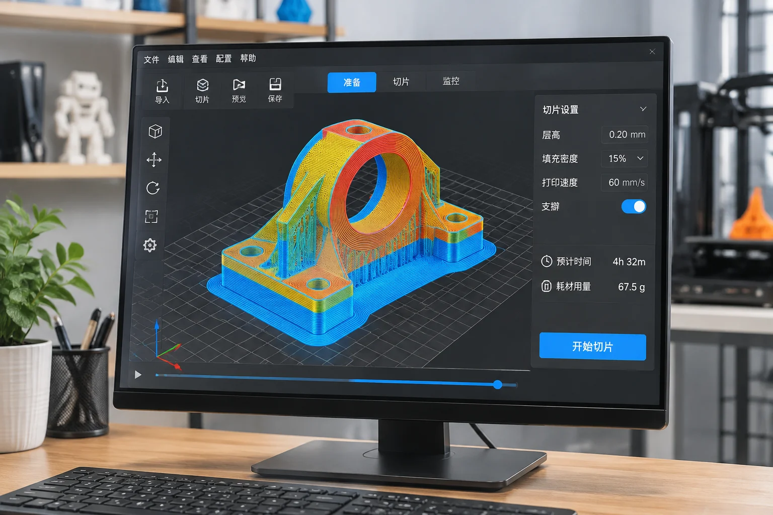
Eliminating Software Drift in Production Print Files
Additive production cells rely on predictable machine toolpaths to maintain consistent tensile strength and surface geometry. Utilizing locked, long-term support release branches of open-source slicing software shields production queues from unexpected toolpath alterations introduced in rolling development builds.
Slicing Environment Verification Points
| Parameter | Value / Technical Scope |
|---|---|
| Release Channel | Long-Term Support (LTS) Tagged Binary |
| Geometry Ingest Format | Direct STEP / ISO/IEC 25422:2025 3MF |
| Perimeter Generator | Arachne Engine with Fixed Tolerance Bounds |
| Seam Placement Strategy | Deterministic Rear-Aligned Coordinates |
| Infill Density & Pattern | Gyroid 25% with Monotonic Top Surfaces |
| Export Checksum | SHA-256 Hash Stored in Build Registry |
- Lock slicer executable versions across every technician workstation to prevent perimeter generation discrepancies.
- Import boundary representation CAD data directly into slicing plates to bypass polygon mesh approximation errors.
- Archive complete slicing profile bundles alongside machine code within the technical project registry.
Establishing Controlled Slicing Workstations
When technicians operate mixed versions of desktop slicing software, machine behavior changes subtly between workstations. Wall overlap calculations, acceleration limits, and dynamic layer fan routines shift noticeably between weekly software builds. In aerospace and technical component production, small modifications to extrusion widths or volumetric limits alter internal density. Slicing engines must therefore run inside standardized, frozen environments with write-protected process presets.
Engineers apply designated project files containing pre-configured support thresholds, layer heights, and cooling profiles. Technicians inspect the simulated toolpath preview layer by layer, verifying travel motions and retraction points before exporting validated machine instructions to the production schedule.
Machine repeatability begins in the digital toolpath generator; uncontrolled software updates create more geometric defects than mechanical component wear.