
SLA Layout Guide for Pre-Print Software
Best practices for stereolithography layout architecture, peel force mitigation, and support generation across professional preparation tools.
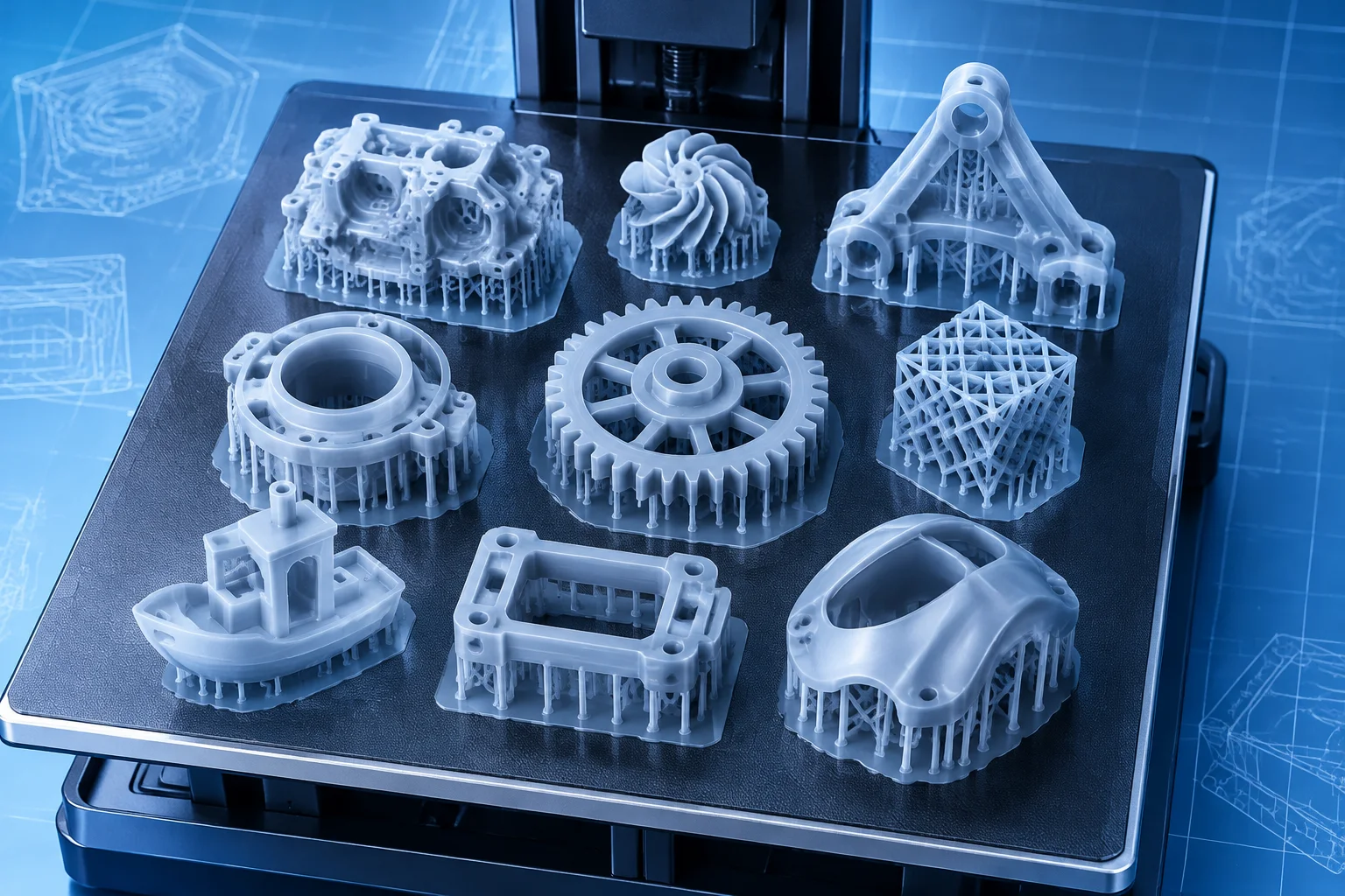
Vat Photopolymerization Platform Arrangement
Preparing complex CAD geometries for vat photopolymerization requires strategic part placement rather than arbitrary nesting. Positioning parts flat against the build plate creates excessive surface contact, producing high suction forces during separation cycles. Tilting parts along compound axes distributes cross-sectional area across consecutive laser passes, preventing layer delamination and geometric warping.
Standard Support and Clearance Metrics
| Parameter | Value / Technical Scope |
|---|---|
| Platform Clearance (Z-Lift) | 4.0 mm – 6.0 mm above raft |
| Nominal Incline Angle (X/Y) | 30° to 45° offset relative to vat |
| Support Touchpoint Diameter | 0.35 mm (fine) to 0.70 mm (structural) |
| Inter-Part Spacing Margin | 3.0 mm minimum resin flow clearance |
| Drainage Hole Diameter | ≥ 2.5 mm on lowest platform facing face |
| Raft Edge Bevel Angle | 45° chamfer for removal blade insertion |
- Angle geometries so local minimums initiate from robust structural ribs instead of cosmetic surfaces.
- Place intentional drainage vent orifices directly at the lowest Z coordinate to equalize fluid pressure.
- Position heavier mass concentrations closest to the build plate to decrease mechanical leverage during peel cycles.
Peel Mechanics and Support Architecture
During the inverted SLA printing cycle, newly cured polymer layers adhere both to the build platform assembly and the flexible vat film. Separation forces peak when large cross-sections disconnect from the silicone or fluoropolymer membrane. Orienting surfaces at thirty to forty-five degrees minimizes the peel area per step. Automated support tools generate scaffolding clusters, yet manual inspection remains mandatory to catch isolated downward islands before slicing completes.
Enclosed volumes act as hydraulic pistons inside liquid resin vats, creating severe pressure imbalances without adequate venting. Hollowed models must feature at least two separate apertures: one lower relief orifice to discharge viscous resin and an upper vent to admit atmospheric air. Omitting these openings results in blown wall sections, distorted features, and resin contamination inside sealed cavities.
Support generation is not merely cosmetic mitigation; it forms the dynamic structural load path counteracting peel forces during vat separation.