
SLS Chamber Simplified 3D Schema Rules
Standardized conventions for diagramming selective laser sintering build envelopes, heater orientations, and powder boundary zones.
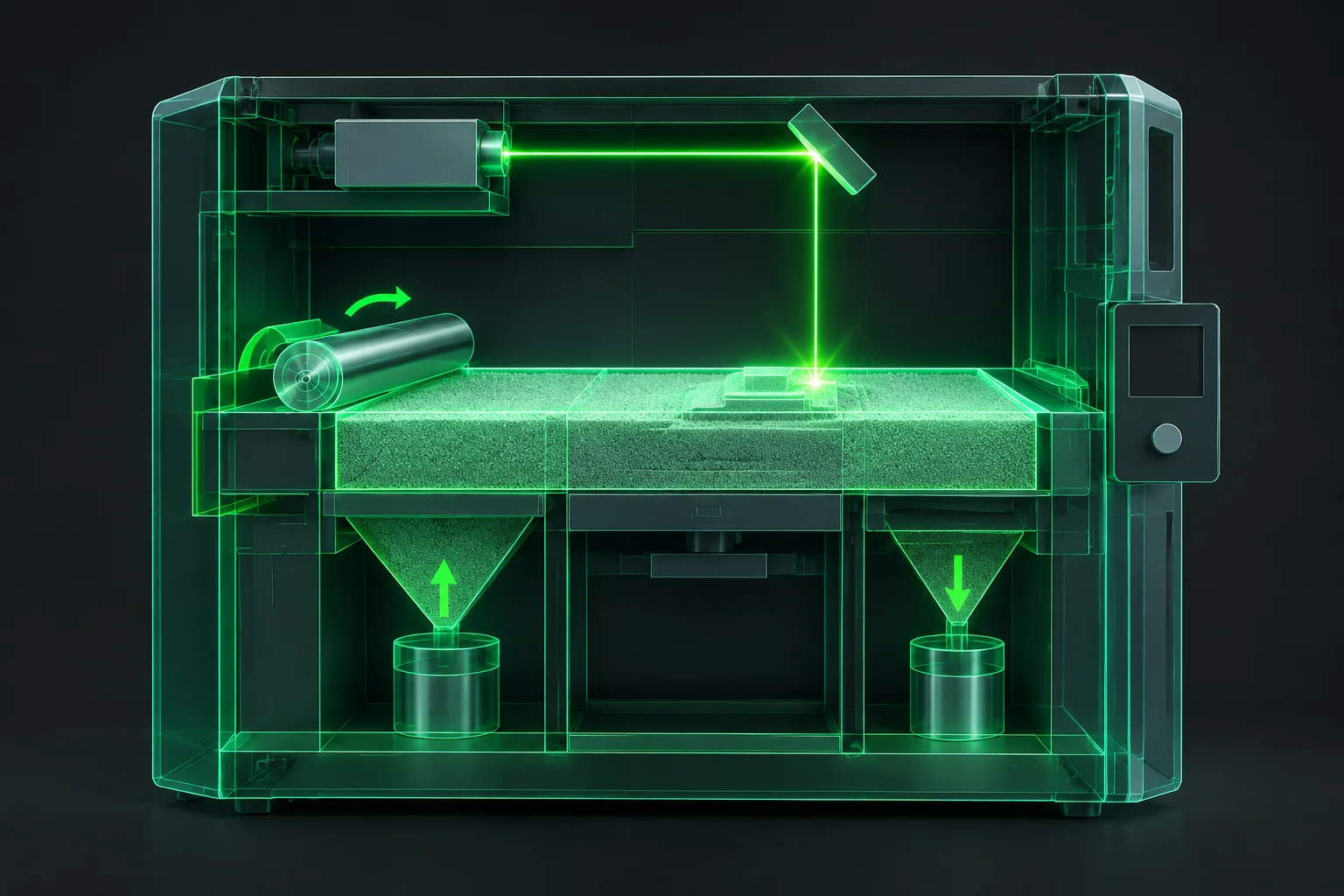
Visual Representation of Powder Envelopes
Clear schematic representations of selective laser sintering (SLS) build volumes require deliberate structural simplification. Complex CAD machinery details such as external chassis panels, mechanical pulleys, and cable harnesses obscure essential production facts. Technical schematics must prioritize usable build height, recoater directionality, thermal heater core distribution, and safe boundary margins. Adhering to unified wireframe conventions ensures operators across shift handovers interpret layout packing density and powder clearing allowances without ambiguity.
SLS Chamber Schematic Parameters
| Parameter | Value / Technical Scope |
|---|---|
| Chamber Axis Alignment | Right-Hand Cartesian (Z+ Build Plate Descent) |
| Usable Envelope Margin | Minimum 10 mm Buffer from Cylinder Wall |
| Recoater Sweep Vector | Arrow Vector with Velocity Annotation (mm/s) |
| Thermal Gradient Overlay | 3-Band Radiative Zone Isoline Representation |
| Wireframe Stroke Weight | 0.75 pt Primary Bed, 0.35 pt Secondary Grid |
| Scale Ratio Requirement | 1:10 Scaled Isometric or Dimensioned Orthogonal |
- Exclude non-functional external framing to preserve visual emphasis on the sinter bed, recoater line, and heater coverage zone.
- Indicate the recoating blade or roller pass direction with a single directional indicator to evaluate shear displacement risks.
- Maintain explicit dimensional labels for the unheated perimeter buffer where sintering produces thermal curl defects.
Preserving Clarity in Multi-Part Density Layouts
When documenting nested production jobs, drafting every part profile inside an active SLS cake creates visual clutter. Simplified 3D chamber schemas replace intricate part meshes with bounding boxes or convex hulls while retaining exact centroid coordinates. This approach isolates critical packing distances, allowing quality controllers to verify whether adjacent components comply with the standard 5 mm inter-part gap.
Furthermore, vertical spacing along the Z-axis demands accurate thermal stabilization tracking. The simplified graphic communicates the warmup base layers, functional print stratum, and top cooling powder reserve as distinct planar divisions. Technicians quickly ascertain whether dense geometry clusters align with the optimal center temperature envelope or risk boundary chilling near the cylinder margins.
A schematic that attempts to model every structural fastener in a powder printer obscures the only geometry that matters: the usable thermal core and the clearance boundaries.